Arduino USB Midi Interface
1 x MIDI IN
1 x MIDI OUT 1 x USB
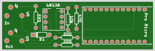
Appears as MIDI interface on PC Mac Linux Android
Fully programmable using Arduino IDE
Comes pre-programmed so works straight away
Ideal for embedding in your project
PCB works with 6N138
Header pins long enough to plug into you own project
(ver3) PCB available seprately as a kit or make your own--> PDF
Expand to create your own controller
Every analogue and digital pin free to use
Media Library


What's in the Kit
Reference
Software & Libraries
Arduino IDE
Control Surface - GitHub
Pre-loaded Arduino Sketch
Test the MIDI in
Arduino IDE
Control Surface - GitHub
Pre-loaded Arduino Sketch
Test the MIDI in
Printed Circuit Board
PCB Artwork - Works Single Sided Etch
ZIP - PDF Normal - PDF Mirrored
Circuit Diagram & breadboard layout
ATmega32U4 Datasheet PDF
5v 3.3v controller 6N138 Confusion LINK
PCB Artwork - Works Single Sided Etch
ZIP - PDF Normal - PDF Mirrored
Circuit Diagram & breadboard layout
ATmega32U4 Datasheet PDF
5v 3.3v controller 6N138 Confusion LINK
Stuff you need
Hand Tools
1 x Soldering Iron & Solder
1 x Side Cutters
Other Stuff
MIDI Cable
MIDI Instrument or controller
Computer with USB socket and Internet Access
Be Careful
Music equipment is expensive.
Check your work against the pictures.
You can't really go wrong.
But it is your responsibility :-)
1 x Soldering Iron & Solder
1 x Side Cutters
Other Stuff
MIDI Cable
MIDI Instrument or controller
Computer with USB socket and Internet Access
Be Careful
Music equipment is expensive.
Check your work against the pictures.
You can't really go wrong.
But it is your responsibility :-)
Assembly Instructions
1
Smallest parts first
Diode - must go in this way round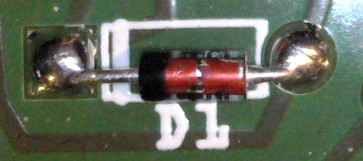
Resistors - check the colour code
6n138 - must go in this way round
Round dot next to square pad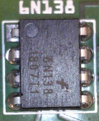
Diode - must go in this way round
Resistors - check the colour code
6n138 - must go in this way round
Round dot next to square pad
2
Solder header sockets to PCB
This depends on how you want to use the board.
This depends on how you want to use the board.
If you want to expand and add or remove the ProMicro later solder these sockets - 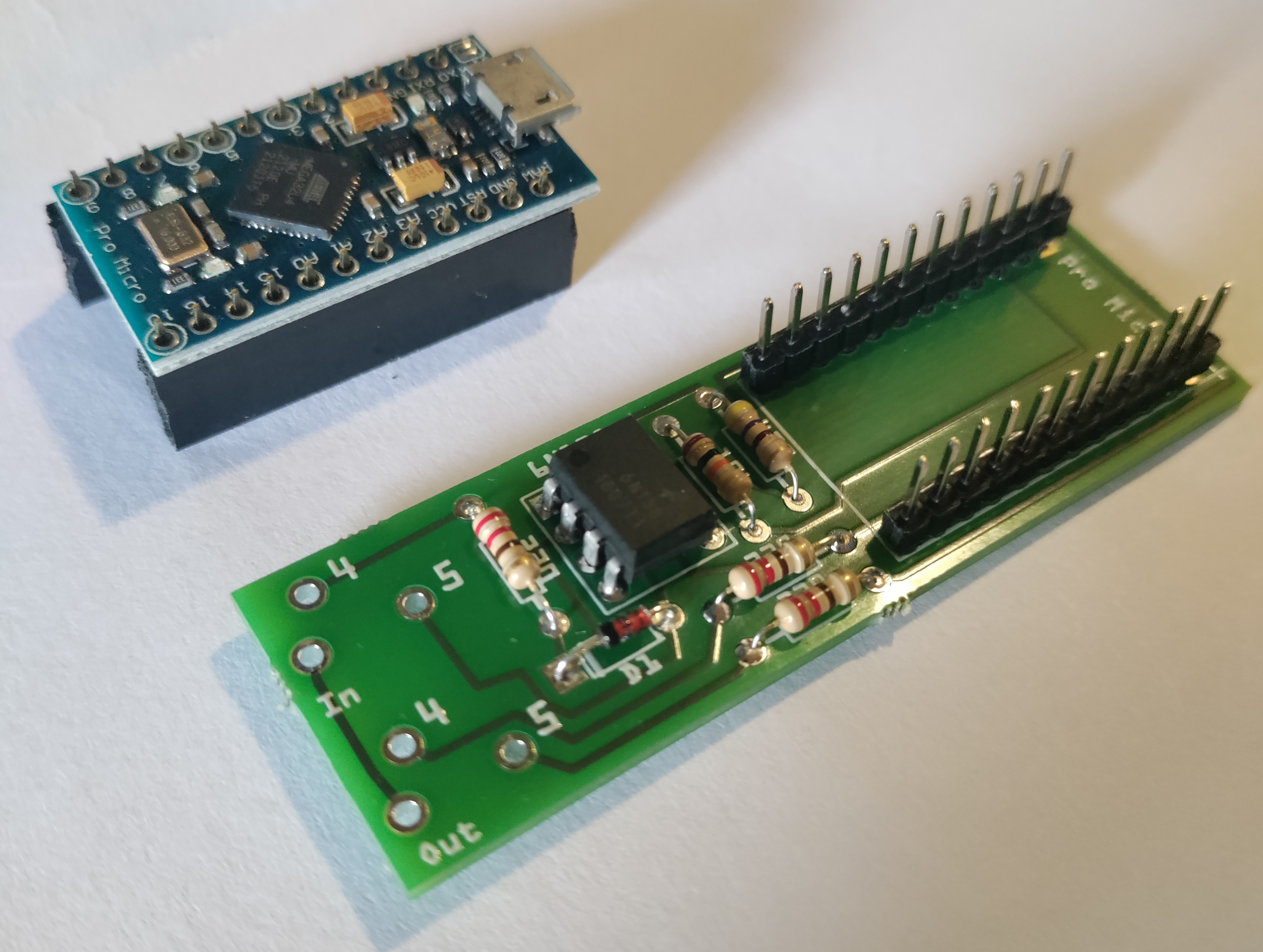
If you want it small and non removable just solder the header pins ready to receive proMicro - IMAGE
3
Solder sockets
3.5mm Stereo Jacks
Or
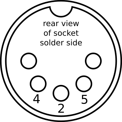
5 Pin Din Sockets
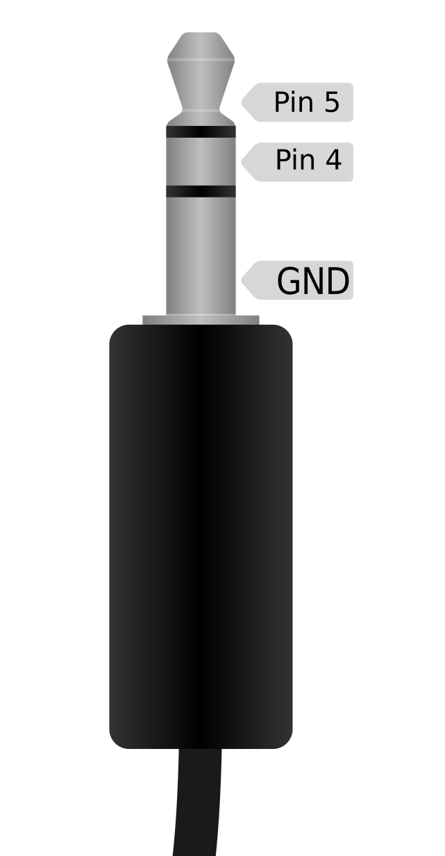
3.5mm Stereo Jacks
Or
5 Pin Din Sockets
4
Solder headers to PCB
5
Check your work before you power it up.
1 - Check soldering with maginfine glass
2 - Make sure orientation of components matches photos
3 - Connect the USB socket to a computer
1 - Check soldering with maginfine glass
2 - Make sure orientation of components matches photos
3 - Connect the USB socket to a computer